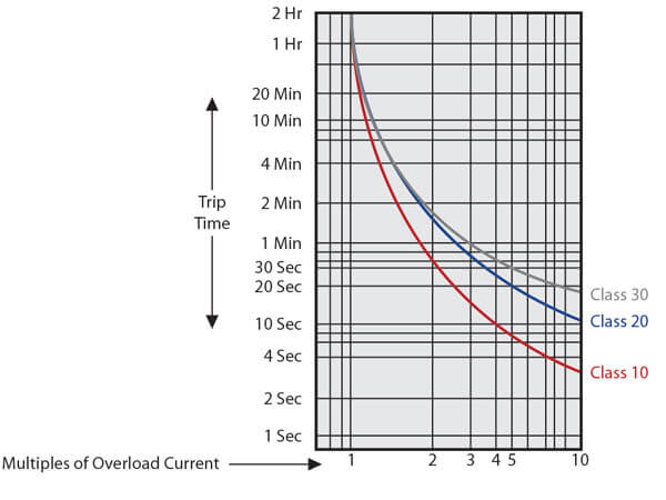
Product Documents & Software Documents, Catalogs & Brochures DigestPlus Online Catalog CAD, Drawings & Curves Browse FAQs Installation & User Guides Software & Firmware BIM (Building Information Modeling) TimeCurrent CurvesIt is commonly classified into Class 10, Class , Class 30 and Class 5 The OLR trips in 10 seconds, seconds, 30 seconds and 5 seconds respectively at 600% of full load current to the motor Class 10 and Class are very commonly used ones Class 30 overload relays are used for protection of motors driving high inertia loads and Class 5 relays are used for the motorsA = 190 superimposed on the running overload curve is an almost exact fit It shows that a longtime inversetime overcurrent relay applied with minimal coordination margin can provide conservative overcurrent protection for motor overload 1000 100 10 1 01 Seconds 1 2 25 3 35 4 4515 Current Running Overload

Differences Between Trip Classes Id Industry Support Siemens
Class 10 overload trip curve
Class 10 overload trip curve-MCB (Miniature circuit breaker) is a resettable device designed to protect a circuit from short circuits and overcurrents The trip curve of an MCB's (B, C, D, K and Z curves) tell us about the trip current rating of Miniature Circuit breakersTrip current rating is the minimum current at which the MCB will trip instantaneouslyA Class 10 overload relay, for example, has to trip the motor offline in 10 seconds or less at 600% of the full load amps (which is usually sufficient time for the motor to reach full speed)


2
Second, look at the class and class 30 trip curves, Fig 31, page 35 For 1000 seconds and up, there is not much difference in the curves Either overload will trip about the same time on long term overloadHow ever, there may be some differences in the values for any oneIn circuit breaker siemens 3wn6173 Reply Jamie says at 600 PM Hey all, I was wondering why my overload relay in an air compressor with a star delta starter is downsized compared to the motor fla?
A Class 10 overload relay will trip in 10 seconds or less at a current equal to 600 percent of its rating correction curve, the correction factor in this case is Table 153 shows that this value falls between 280 A (W63) and 300 A (W64) Because 280 A is closer to the requirement, select theEaton's XT electronic overload relays allow you to select these options right on the face of every overload relay Imagine the amount ofClass 10 Class Class 30 1000 100 10 10 Multiples of FLA 100 Trip Times (s) Figure 1 Typical Trip Curves Motor Current Overload Relay Motor Damage SCPD 1000 100 10 10 Multiples of FLA 100 Trip Time (s) % NEMA 1051% IEC Run Current Starting Current Ic Figure 2 Typical Coordination Curves Product Description
Be careful You may not have the overload protection you think you have Two new requirements for overload and stall time that were added to the NEMA MG1 Standard may be in conflict with actual performance requirements for overload relays as specified in the NEMA ICS 2 StandardWhat it's aboutIn 1993, NEMA published the current edition of its MG1 standardEaton C440B1A100SF3 Overload Relay, Freedom,Size 3, 55 mm, 10 Amp, Class 10 ,, 30 C440 Electronic, Overload Relay Nema, Freedom Size 3, 55 mm Frame, Selectable 10Overload Relays Solid State ESP0, Class 48, 958, 958L and Bimetal General 9/66 Siemens Industry, Inc Class 10 Catalog Number List Price $ Class Catalog Number CLASS 958, 958L Trip curve depending on unbalance CLASS Time Current Characteristics


2


Thermal Overload Relays Circuit Breaker Selection Contactor Selection Additional Automation Functions Dimensions And Schemes Cross Manualzz
Ples of overload relay trip current NEMA has classified overload relays in three classes 1 NEMA Class 10 for protecting submersible pump motors, hermetically sealed refrigeration motors, etc, trips in less than 10 seconds at 6 times trip current 2 NEMA Class for protecting standard motors trips in less than seconds at 6 times trip current 3 NEMA Class 30 trips in less than If it could be put in relative terms, an overload relay providing adjustable trip class may provide curves for say trip classes 10 and 15, but the thermal withstand curve of the connected motor may fall somewhere between the twoTimeCurrent Curves Cables The TimeCurrent Curves for cables are also known as "Damage" curves Cargill Electrical Team Meeting 11 operation of a device was caused by an overload rather than a fault condition, no examination of the circuit or connected equipment is needed before the circuit is reenergized 64 65
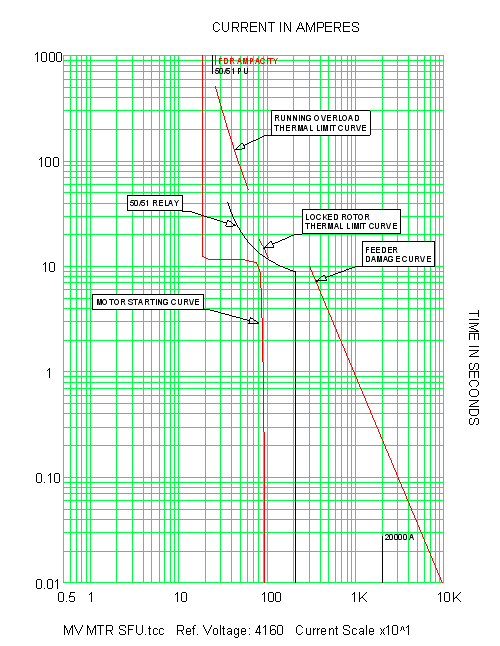


Skm Power Tools Electrical Engineering Software


2
Selectable trip class (10A, 10, , 30) Direct mounting to NEMA, IEC, and DP contactors Most compact electronic overload in its class Motor Control Two B600 alarm (NO) and fault (NC) contacts Test/Trip button Motor Protection Thermal overload Phase loss Selectable (ON/OFF) phase unbalance Selectable (ON/OFF) ground fault User InterfaceSpecific Applications may require Class 10 or Class 30 overload relays Class 10 overload relays are often used with hermetic motors, submersible pumps, or motors with short locked rotor time capability Class 30 overload relays should be used with motors driving high inertia loads, where additional accelerating time is needed and the safe NEMA Standard MG1 defines 4 types of Classes The most common classes are 5, 10, & 30 Class 5, 10, & 30 overload relays will trip within 5, 10, & 30 seconds respectively at 600% of motor full load amps A Class 10 overload relay, for example, has to trip the motor offline in 10 seconds or less at 600% of the full load amps (which is usually sufficient time for the


Soft Starter Thermal Protection
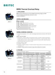


Technical Information Trip Curves For Thermal Overload Relays
Trip classes CLASS 10 CLASS 10, CLASS CLASS 5, 10, , 30 Adjustable CLASS 5, 10, , 30 Adjustable Thermal overload releases A A 011 016 to 80 100 Solidstate overload releases A A 01 04 to 160 630 01 04 to 160 630 03 3 to 63 630 Rating for induction motor at 400 V AC kW kW 004 to 45 004 009 Up to 90 450Curve The unit will trip after a delay determined by the TC (trip class) For standard motors, the TC is typically set at class 10 The motor manufacturer should be contacted for exact TC settings The following curves show the range of TC settings and trip times OVERLOAD TRIP CURVES 500 400 300 0 100 100 125 150 175 0 CLASS 15 CLASS 10Product Documents & Software Documents, Catalogs & Brochures Browse FAQs CAD, Drawings, & Curves Manuals & User Guides Software & Firmware BIM (Building Information Modeling) Digital Platforms Mobile Apps mySE Portal opens in new Window mySchneider app mySchneider Schneider Electric Exchange


What Are The Differences Between The Various Tripping Classes Of Thermal Overload Schneider Electric India


Ie3 Ie4 Motors Selecting The Right Control And Protection Components Ee Publishers
• Trip Curves predict the behavior of circuit protection devices in both slower, smaller overcurrent conditions, and larger, faster over current conditions • Choosing the correct trip curve for your application provides reliable circuit protection, while limiting nuisance or false trips This paper is a brief overview of trip curves Simply put the Class rating specifies in what amount of time the overload will trip after it is in an over amperage situation For example, a Class 10 overload will trip in 10 seconds or less (depending on the percentage variation of AMP pull) and a Class will trip in seconds or less So why is this important and how do you know which to choose? If the motor in the example from step 2 had a service factor of 115 then its overload would be acceptable and the motor could be operated without damage Check the motor nameplate for the ambient temperature rating and the insulation class ratings Electric motors are commonly rated for operation in an ambient temperature of 40 deg C (104 deg
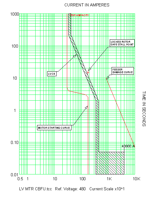


Skm Power Tools Electrical Engineering Software
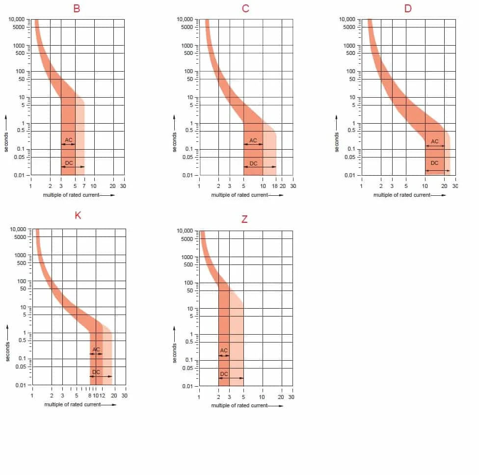


Mcb Trip Curves B C D K And Z Trip Curves Made Easy
LRD08 from Schneider Electric at Allied Electronics & Automation * Products listed as "People Also Bought" are not recommended accessories andOverload Relay Trip Curves Selection Index Class 2510, 8536, 9065 Overview Overload relay trip curves present trip time as a fu nction of overload current To use them properly, you must understand their application, construction, and limitationsAdd up all the thermal overload relays it would take to cover 03 to 100 amps, class 10, class , class 30, and class 10A with automatic and manual reset It would take 214different thermal overload relays!
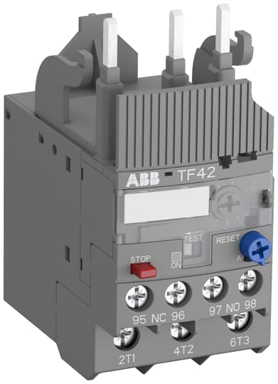


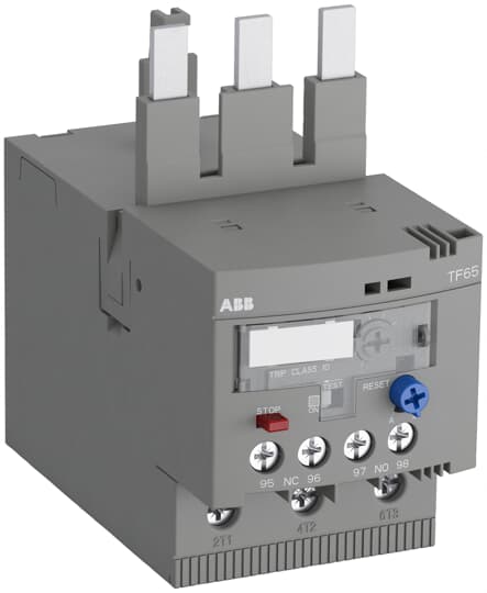
Tf42 10 Abb


2
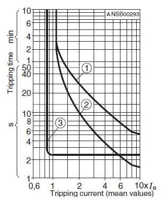
3) For overload protection of the motors, appropriate overload relays must be used 4) According to UL 4 at 480 Y/277 V AC for size S0 50 kA, for size S3 65 kA;at 480 VAC for size S3 (10 A up to 30 A) 65 kA 5) Only lateral auxiliary switches can beOperating Principle Overload or thermal protection is I 2 t IDMT (Inverse Definite Minimum Time) o It incorporates the motor thermal image function o It can be configured as the Ir pickup and as the trip class (Class) Tripping curveThe TF4210 thermal overload relay is an economic electromechanical protection device for the main circuit It offers reliable and fast protection for motors in the event of overload or phase failure The device has trip class 10 Further features are the temperature compensation, trip contact (NC), signal contact (NO), automatic or manual


Suggestion On How To Use Ppt Descargar


3ua Thermally Delayed Overload Relays
What is formula of curve of overload protection class 10?Electronic thermal overload relays For use with TeSys D contactors Adjustable electronic overload relay, Multiclass, multiscale TeSys LR9D From 01 to 150 A B11/10 Electronic thermal overload relays For use with TeSys F contactors Compensated and differential overload relays, with or without alarm TeSys LR9F From 50 to 630 A B From industrial to construction applications, Siemens offers a wide range of overload relays Our NEMA class of overload relays are used to protect motors from the cold, such as refrigeration, where the ESP0 uses its auto reset mode to help you avoid shutdowns To protect motors against overheating, the ESP0 also has phase unbalance protection and thermal


Skm Power Tools Electrical Engineering Software


Overload Relay What Is Overload Protection C3controls
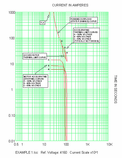
Digitize your curve and interpolate for 5, 6, 8, 10, 11, 13, and 14, unless you can get it from the manufacturer There are no standard values RE Overload Curves Table ScottyUK (Electrical) 6 Are the numbers 1 15 just arbitrary numbers or do they have some relationship to the curve, ie are they multiples of setting current 40°C 10°C Class B 80°C 130°C Class F 155°C 40°C 15°C Class F 105°C 160°C Class H 180°C Accelerating Curve The accelerating curve represents the starting and running ampere characteristic curve of a motor for a given load inertia (Wk2), load torquespeed curve, and Running overload curves are typically provided for mediumvoltage10 Motor Thermal Limit Curves Thermal Limit Curves B Hot Running Overload B A Cold Running Overload A D D Hot Locked Rotor Curve C C Cold Locked Rotor Curve F Acceleration curve @100% voltage F E Acceleration curve @ 80% rated E voltage • Thermal Limit of the model is dictated by overload curve


Differences Between Trip Classes Id Industry Support Siemens


Technical Information Trip Curves For Thermal Overload Relays
Curves The fuse specification typically will include a life requirement at 100% of rating and maximum opening times at overload points (usually 135% and 0% of rating depending on fuse standard characteristics) A timecurrent curve represents average data for the design;OVERLOAD ADJUSTMENT DIAL MARKINGS 27 24 22 18 15 13 Class 10, and 30 trip curves are available for a variety of applications The ESP100 solid state overload provides phase loss protection for the motor by tripping within three seconds upon complete loss of one phase of aCurve The unit will trip after a delay determined by the TC (trip class) For standard motors, the TC is typically set at class 10 The motor manufacturer should be contacted for exact TC settings The following curves show the range of TC settings and trip times OVERLOAD TRIP CURVES 500 400 300 0 100 100 125 150 175 0 CLASS 15 CLASS 10


Lr9f7375 Tesys Lrf Electronic Thermal Overload Relay 0 330 A Class 10 Schneider Electric Global


Overload Or Thermal Protection Ansi 49
AGN 013 ISSUE C/2/10 For industrial use alternators, two Peak Standby Rating levels are offered, based on temperature rise limits and ambient temperatures that provide a total temperature 10°C above the total temperature limit for the insulation system For low voltage alternators ClassThe heater packs are securely held in the overload relay by two captive screws Three Class (Class 10 optional) heater packs are installed in the overload relay The 32 ampere heater packs will mount in the 75 ampere overload relay for applicationsB) A Motor Thermal Withstand Curve is provided With this information available to you, you can refer to the tables given in IEC to identify the most appropriate Overload Trip Class This is defined as the one that provides a trip curve as close as possible to but below the overload curve


Ct7n Bimetallic Thermal Overload Relays From Sprecher Schuh


Differences Between Trip Classes Id Industry Support Siemens
Loading Please enable javascript or update your browserOE = Electronic overload relay Mounting Blank = Direct to contactor S = Separate mount (Frames C and G only) Trip Type CS = Selectable Class 10A, 10, , 30 GS = Ground fault with selectable Class 10, Overload Release Contactor Frame 1P6 = 033–165A 005 = 1–5A 0 = 4–A B = 45 mm 1P6 = 033–165A 005 = 1–5A 0 = 4–A 045 = 9 So Class 10 is 10 seconds, Class is seconds, Class 30 is 30 seconds This then, in the design of the motor, relates to what is referred to as the "thermal damage curve" of the motor, the combination of current and time that will create enough heat in the motor to damage the winding insulation
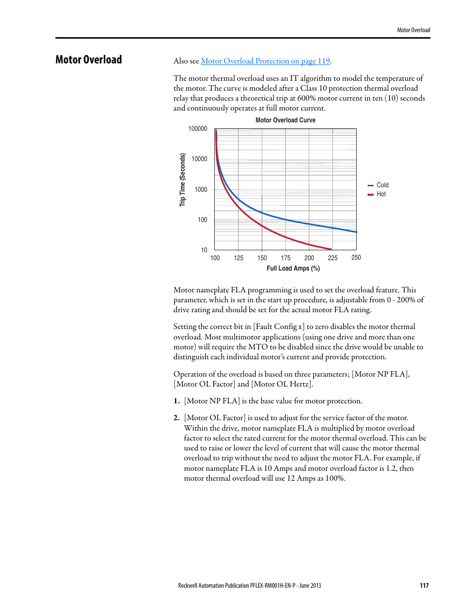


Motor Overload Rockwell Automation b Powerflex 70 Powerflex 700 Reference Manual User Manual Page 117 214
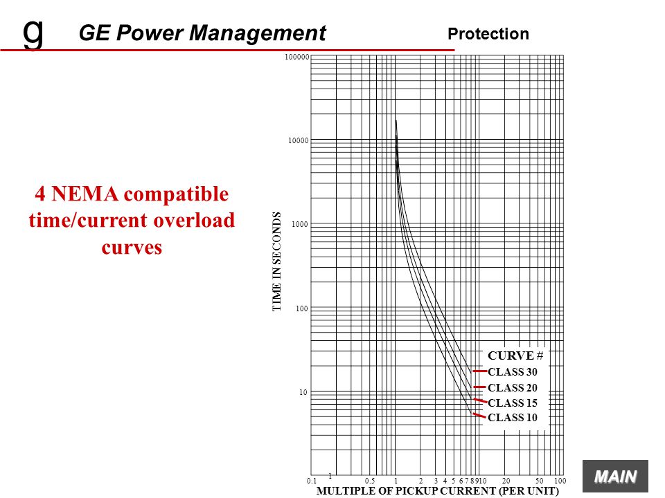


G Ge Power Management Mmii Intelligent Mcc Controller Ppt Video Online Download
Thermal Overload Relay Trip Characteristics Melting alloy and bimetallic overload relays are designed to approximate the heat actually generated in the motor As the motor temperature increases, so does the temperature of the thermal unit The motor and relay heating curves (in the figure Overload Relay Trip Curve) show this relationshipTripping curves (cold or warm starting, 3 phases and 2 phases) Class 10 4 10 sec 12 Ie 72 Ie Class 6 sec Thermal Overload Relays with Trip Class Resistances and power losses per phase Shortcircuit protection Thermal overload relay T5DU trip classValues for the different Class Motor Overload protections Class 10 trip curve is 350 s" ", for a Class trip curve "700 s", and for a Class 30 trip curve "1050 s" The parameter 3552 (Zero speed load) defines the motor load curve


2


Soft Starter Thermal Protection
Normal starting time class 10 TA110DU SB 7398 TA80DU SB 7399 T5DU 2CDCF0003 T7DU SST T00DU SST032 99 T5DU 7386 SB 7361 , check suitability on the basis of the tripping curves The values for Tripping curve of overload relay T


Lr9d5367 Tesys Lrd Thermal Overload Relays 60 100 A Class 10 Schneider Electric Global


Overload Or Thermal Protection Ansi 49


Overload Or Thermal Protection Ansi 49
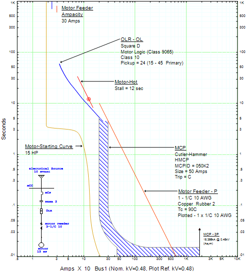


Lv Motor Protective Device Settings Lv Motor Video Tutorial


Differences Between Trip Classes Id Industry Support Siemens


Iec 4 1 Tripping Time Curves As A Function Of Actual To Full Load Download Scientific Diagram


2


What Is Trip Class Trip Classes 5 10 10a 30 40 Explained


Lr9d67 Tesys Lrd Electronic Thermal Overload Relay 60 100 A Class 10 Schneider Electric Global


2


Thermal Overload Relay 1 25 2amp Nr2 25 Chint


Figure 5 From Single Phasing Protection Of Line Operated Motors Of Different Efficiency Classes Semantic Scholar


Skm Power Tools Electrical Engineering Software


Motor Protection How To Calculate Thermal Overload Trip Time For Relay Youtube


2


Iec 4 1 Tripping Time Curves As A Function Of Actual To Full Load Download Scientific Diagram


Lrd22 Relays Datasheet Pdf Overload Relays Equivalent Catalog


Technical Information Trip Curves For Thermal Overload Relays


Table I From Single Phasing Protection Of Line Operated Motors Of Different Efficiency Classes Semantic Scholar


Working Principle Of Thermal Motor Protection Relay
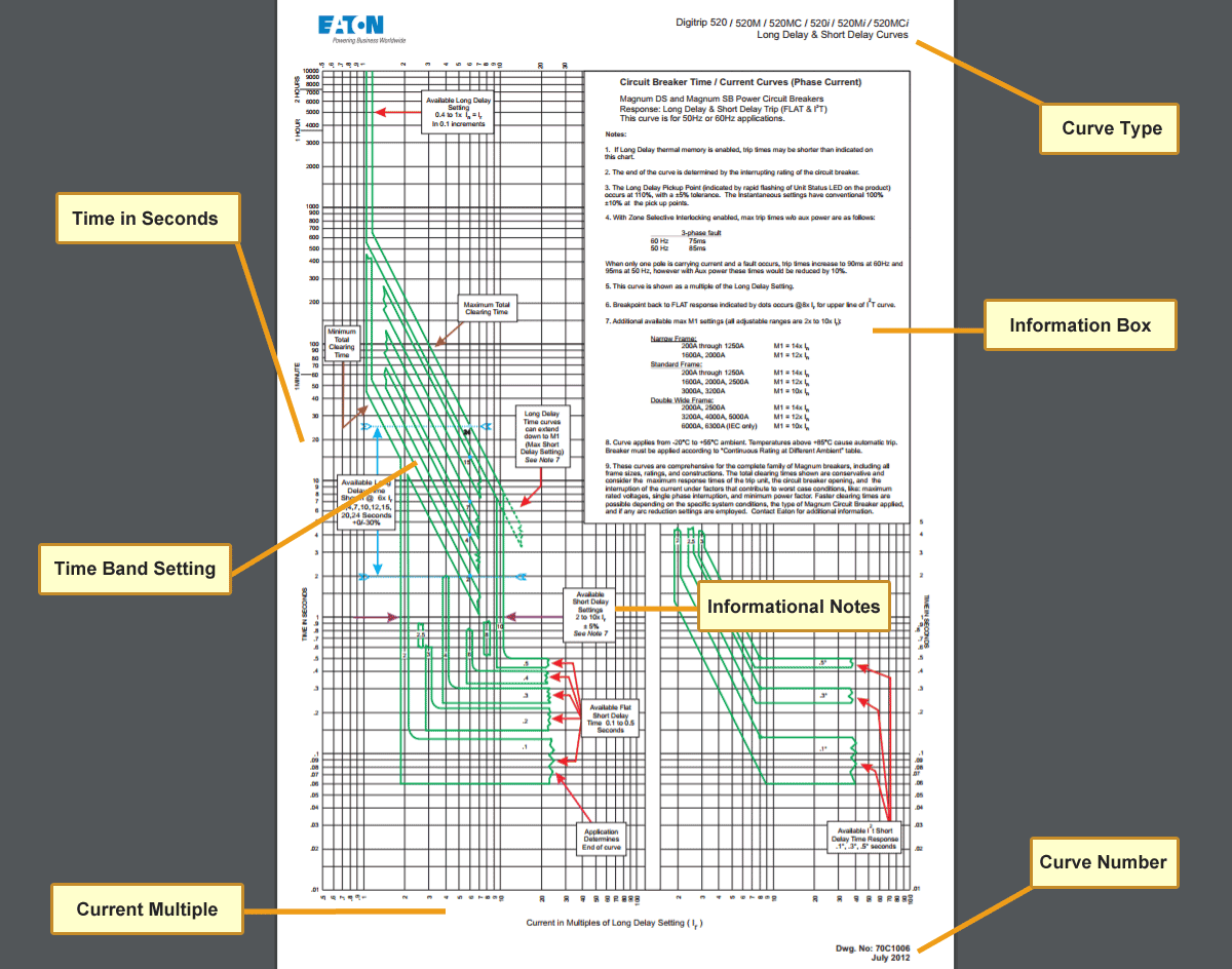


Characteristics Of Circuit Breaker Trip Curves And Coordination


1


North America Nema Classes And Ansi Tripping Curves


Overload Or Thermal Protection Ansi 49


2
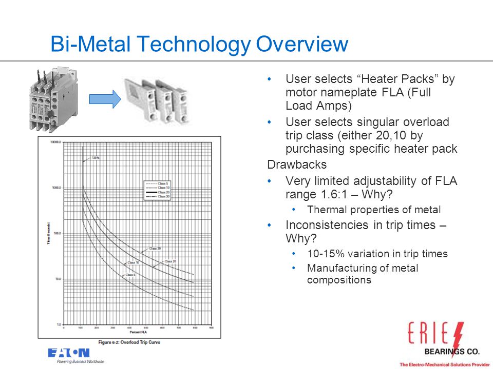


5 Ways To Protect Your Motor And Increase Your Uptime With Solid State Overload Relays Hosted By Erie Bearings Adam Krug Product Manager Industrial Ppt Download


Type A Ac Class Rcbo 110v 2v Rccb 10a a 40a 50a 63a 30ma Residual Current Circuit Breaker Leakage With Overload Protection Circuit Breakers Aliexpress


Thermal Overload Relay Class 10 A 8 A For 3 Pole Mini Contactors Ctx 4 170 Legrand


Motor Thermal Overload Protection Electrical4u


Tisoft Tripping Curves


What Are The Differences Between The Various Tripping Classes Of Thermal Overload Faqs Schneider Electric India


2


Thermal Overload Motor Relay Protection


Iec 4 1 Tripping Time Curves As A Function Of Actual To Full Load Download Scientific Diagram


Powertips Thermal Overload Relays For Motors


Thermal Overload Relay Ekr2 China Changan Electric


2


Thermal Overload Relay Class 10 For Abb Contactors A Af300 Overloads Ecd Controls


Tripping Curves Of A Commercial Bm Tor Of Class 10 A 25 Download Scientific Diagram


Ls Thermal Overload Metasol 95 130 Amp Tro Pacific


2


Class 10 Overload Curve


2
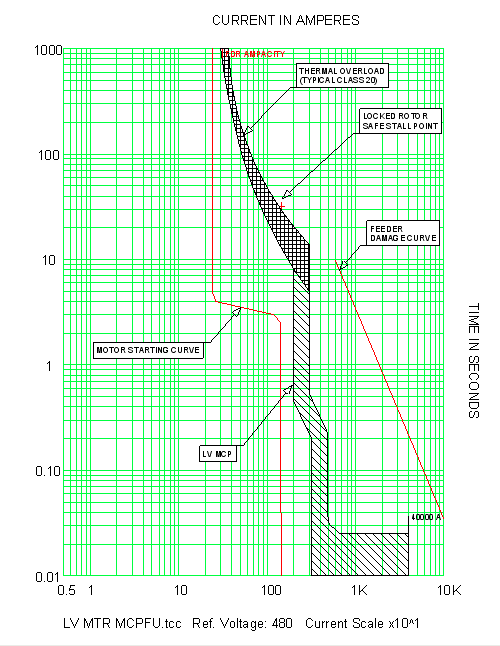


Skm Power Tools Electrical Engineering Software
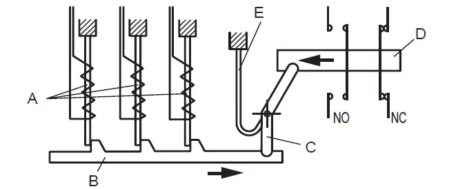


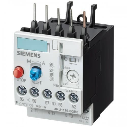
Overload Relay Principle Of Operation Types Connection


Iec Trip Curves Iec Curve A


1


2


2
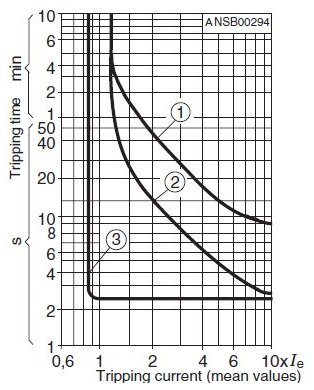


Tisoft Tripping Curves
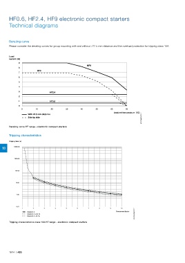


Page 796 Motor Protection And Control Manual Motor Starters Contactors


2


2


Tripping Curves Of A Commercial Tmcb Of Class 10 31 Download Scientific Diagram


2
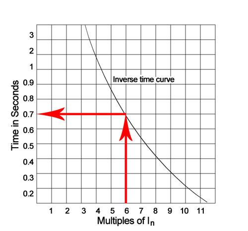


Characteristics Of Circuit Breaker Trip Curves And Coordination


2


2


In The Standard Blokset Mcc Coordination Tables The Type Of Overload Relays Used Is Class 10 Only If Customer Specifies Class Or Class 30 What Should We Do Faqs Schneider Electric Aps Global
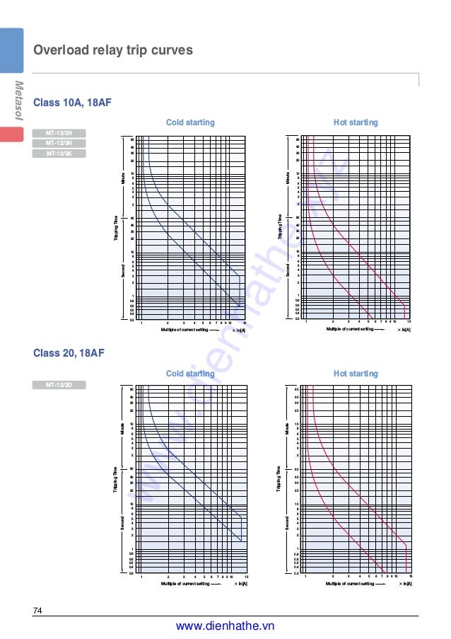


Overload Protection Relays Ls Metasol Overload Relays Mt 32 3k Trip Class 10 Business Industrial


Ppt Abb Softstarter Benefits Charnchanok Thongprad Powerpoint Presentation Id


Motor Starters Overload Relay


1


Newelec Pretoria Pty Ltd The Newelec La Electronic Motor Protection Relay Provides Superior Thermal Overload 50 And Phase Unbalance And Single Protection In Applications That Would Traditionally Have Used Thermal Bi Metal


Media Distributordatasolutions Com


Gv2p14 Motor Circuit Breaker Tesys Deca 3p 6 10 A Thermal Magnetic Screw Clamp Terminals Schneider Electric Global
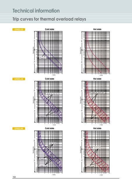


Technical Information Trip Curves For Thermal Overload Relays
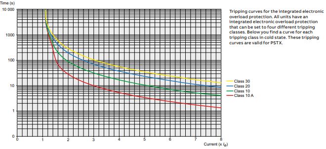


Abb Soft Starters Pstx Series Buy In Asb Drives Low Prices
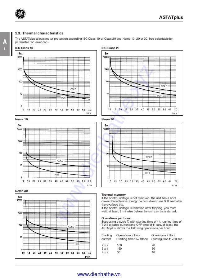


Cataloge Ge 3 Control And Automation Dienhathe Com 5 Softstarters Ast


Differences Between Trip Classes Id Industry Support Siemens


2


2


Tf65 40 Abb


Ct8 Thermal Overload Relays From Sprecher Schuh


Differences Between Trip Classes Id Industry Support Siemens


Tisoft Tripping Curves


Overload Relay Principle Of Operation Types Connection


Motorsandcontrol Com


0 件のコメント:
コメントを投稿